


Enabling switch for installation and enabling switch in handle, 3-stage


3-stage operation Enabling switch (IEC 60947-5-8)
The functionality of our enabling switches is 3-step or based on 3 positions. The working contacts are actuated in the middle position. For this purpose we have implemented a clearly perceptible pressure point on the design side. In case of panic action / injury the operator would either press firmly (3rd stage) or release the handle (1st stage). Both times the working contacts would be deactivated and thus the system would be stopped. The 2nd stage must therefore be actively operated and held. It is mainly used when setting up or maintaining machines or robots within danger zones.
3-stage function for safe maintenance of machines
There can always be reasons to deactivate the protective device in the danger area of machines and industrial plants, e.g. for maintenance and repair. This means whenever operating personnel must work directly in these danger zones to carry out programming, testing or service work. A distinction is also made here between – mostly automatic – normal operation and manual special operation. In most modern industrial plants, “normal” operation stands for automatic functions, e.g. with robots. This is where the operational safety measures take effect. These lead to a standstill of the machine if a person enters the danger area or the safety door opens.
But does it come to the…
- new installation
- Process changeover
- Fault correction
- Maintenance
- Programming
…then the normal safety devices must be removed and the machine must be controlled in manual mode. In order to protect persons and equipment from damage, the so-called enabled buttons are used. This is because if the safety devices of normal operation are deactivated, additional measures must be taken to ensure personal protection in special operation as well. These include above all the 3-stage enabling switches.
Their use is prescribed in the machine directives, appendix 1, as soon as the protective device is lifted in these operating modes. The directives state that a lockable device must be used here, which only enables the machine operation by a second, separate action. So if an operator in the danger area is able to move the machine, the enabling switch must additionally be confirmed in form of a manually operated control device. Every person working in the danger area must carry this enabling device with him/her.
How 3-step enabling switches work

The main task of the enabling switches is to prevent personal injury and damage to property in the event of uncontrolled or unforeseeable machine movements. In panic, people react either by pressing the switch forcefully or by releasing it completely: both will reliably switch off the machine.
The functionality of our enabling switches is 3-step or based on 3 positions. The so-called OFF-ON-OFF function – i.e. the 3-stage version – is regulated by international standards.
-
- level 1: the button is not yet pressed. Machine is either deactivated (Off) or runs with activated safety functions of normal operation
- level 2: the middle position of the enabling switch. In this case, the machine runs while the separating safety devices such as doors are deactivated to allow maintenance work or new settings to be made (On)
.
-
- Level 3: If the switch is pressed too hard or pushed through, the machine is brought to a stop (Off). In this way, the enabling switch protects the operator and the persons in the danger area if an overreaction occurs in a startle situation
.
The working contacts are actuated in the middle position. For this purpose, we have implemented a clearly perceptible pressure point on the design side. In the event of a panic action / injury, the operator would either press down firmly(3rd stage) or release the handle (1st stage). Both times, the working contacts would be deactivated and thus the system would be stopped. The 2nd stage must therefore be actively operated and held. Only then is the special manual operation of the industrial plant possible, while the normal safety devices are deactivated during maintenance, programming or process changeover. The use of an enabling switch is therefore mainly used when setting up or maintaining machines or robots within danger zones.
The 3-stage operating principle is thus based on the ergonomic viewpoint from which an operator in a shock situation, such as an electric shock, or even a heart attack, would either press too hard or release it abruptly.
Another safety requirement for an enabling switch is that the contacts are not closed when resetting from step 3 to 1 in step 2, so that the machine is not briefly activated.
The 3-step enabling switches from B-COMMAND are characterized by the following advantages:
- Exemplary ergonomics
- Low weight
- Light, stable pressure point
- 2 working circuits (redundancy)
- Auxiliary contacts for monitor functions
- Hard to manipulate
- actuating force from position 2 (on) to position 3 (off – if too tight) for centric and eccentric pressure identical
Most of the enabling switches have redundant switching contacts and redundant actuators. The deviation of the switching states of both contacts can be detected as a fault by means of a suitable circuit and the machine can be put out of operation despite possibly damaged contacts. For optimum operating convenience, the actuating force from position 2 to 3 is absolutely identical for the centric as well as the eccentric pressure: even switching with only one finger at the outer end is reliably possible. In addition, the required operating force changes only marginally even after the 10,000th actuation.

Manufacturing quality and reliability meet IEC 60947-5-8
Although international regulations made it necessary to use 3-stage enabling switches, nothing was specified in terms of the operating force and service life of the switches. Both are, however, of crucial ergonomic importance. All B-COMMAND enabling switches are designed and tested with special attention to long life and maximum safety.
The special requirements of the IEC 60947-5-8 directive formed the basis for the product range. All enabling switches were tested and certified according to the specifications of the directive IEC 60947- 5-8.
Our permission buttons enable also:
- The safe working in the danger zone
- The observation of processes with opened or deactivated separating protective devices (e.g. safety doors). This is important e.g. for process changes or new installations
- Protect the operator and persons working in the danger zone from overreactions in the machine control system
- Comfortable operation thanks to ergonomically shaped housing
Standards & approvals for enabling switches
Enabling switches, which are integrated into safety circuits of an industrial plant, have a personal and plant protection function. The design of the function, as well as the integration and installation in the plant must therefore be based on the Machinery Directive and the European standards. The Machinery Directive has been transposed into national law in the EU member states and is therefore binding for every manufacturer. Precise requirements for switches such as the enabling switch are defined in EN 60947 Part 5-1 (Low-voltage switchgear and controlgear – Part 5-1: Control circuit devices and switching elements; Electromechanical control devices). Only when all these requirements are met or even exceeded (durability and ergonomics) may they be used. Our enabling switches meet or even exceed all relevant standards for safety switchgear. In this way, we help you to comply with the safety specifications when designing your machines.
European standards
| EN 60 204 | Safety of machinery - Electrical equipment of machines |
| EN 775/ EN ISO 10218 | Industrial robots; Safety (ISO 10218:1992, modified) |
| VDI 2853 | Safety requirements for construction, equipment and operation of industrial robots (withdrawn) |
| VDI 2854 | Safety requirements for automated manufacturing systems |
American standards
| ANSI B11-TR3-2000 | Risk Assessment and Risk Reduction - A Guide to Estimate, Evaluate and Reduce Risks Associated with Machine Tools |
| NFPA 79 (2002) | Electrical Standard for Industrial Machinery |
| OSHA 29 CFR 1910 / Subpart O / Subpart P / Subpart S | Machinery and Machine Guarding Hand and Portable Power Tools and Other Hand |
Approvals and standards of the enabling switches in detail

The manual special mode
If a functional check of the system is to be carried out after an adjustment or maintenance, the manual control mode is a good choice. The transition from automatic mode to manual mode of the system can be initiated, for example, by removing the enabling switch from its wall bracket. We offer this wall bracket for the series ZB1 and ZB2 as an accessory.
Using the control or function keys optionally integrated in the enabling switch, the operator can control the system in manual mode in the danger zone.
The 3-stage function sequence with positive break
In most enabling switches, positive break contacts are used, which describes specially designed switching elements that ensure that the switching contacts are always reliably isolated. This even applies if contacts should be welded. Even then the connection is separated by the actuating force.
As shown in the figure above, the consent function can only be achieved in step 2. This is achieved by closing the normally open contacts by the manual actuation force of the operator. If the operator releases the button in a panic reaction, with the switch jumping from stage 2 (On) back to stage 1 (Off) , the normally open contacts open again.
Until this point, the 2-stage and 3-stage enabling switches are also similar in their function. The difference becomes clear when the operator presses too hard, e.g. in case of a cramp or an electric shock. If a 2-stage enabling switch is used for special manual operation in the danger zone, additional operating elements must be provided to ensure that in an emergency, the person is able to activate a nearby emergency stop device (VDI 2853)..
Now, if the pressure point (stage 2)is overpressed (stage 3>in a case of panic, the difference becomes clear. Here, not only the normally open contacts (S) are reset, but also the safe positively driven contacts (Ö ) are opened. In addition, it is ensured that when resetting from level 3 to level 1 at the pressure point at level 2 at the pressure point, the enabling function is not activated. This is because the enabling function can only be activated if the normally open and positively driven contacts are closed simultaneously. This is only possible when operating from stage 1 to stage 2. In the reverse direction, from stage 3 to stage 1, stage 2 is skipped and thus an unintentional restart is prevented. Once the control unit has reached stage 1, the function sequence can be restarted.
Some enabling switches can also be equipped with an optional emergency stop switch.
Ergonomics of our enabling switches
The great advantage of our enabling switches is the balanced handling, even over longer periods of time (e.g. when observing production processes). Low weight, ergonomic housing design and a light, stable pressure point and low-wear contacts ensure a long service life and safe operation in all situations. The ability to operate with several fingers, instead of just the thumb, maintains the actuating force even over longer periods of time.
Our enabling switches at a glance
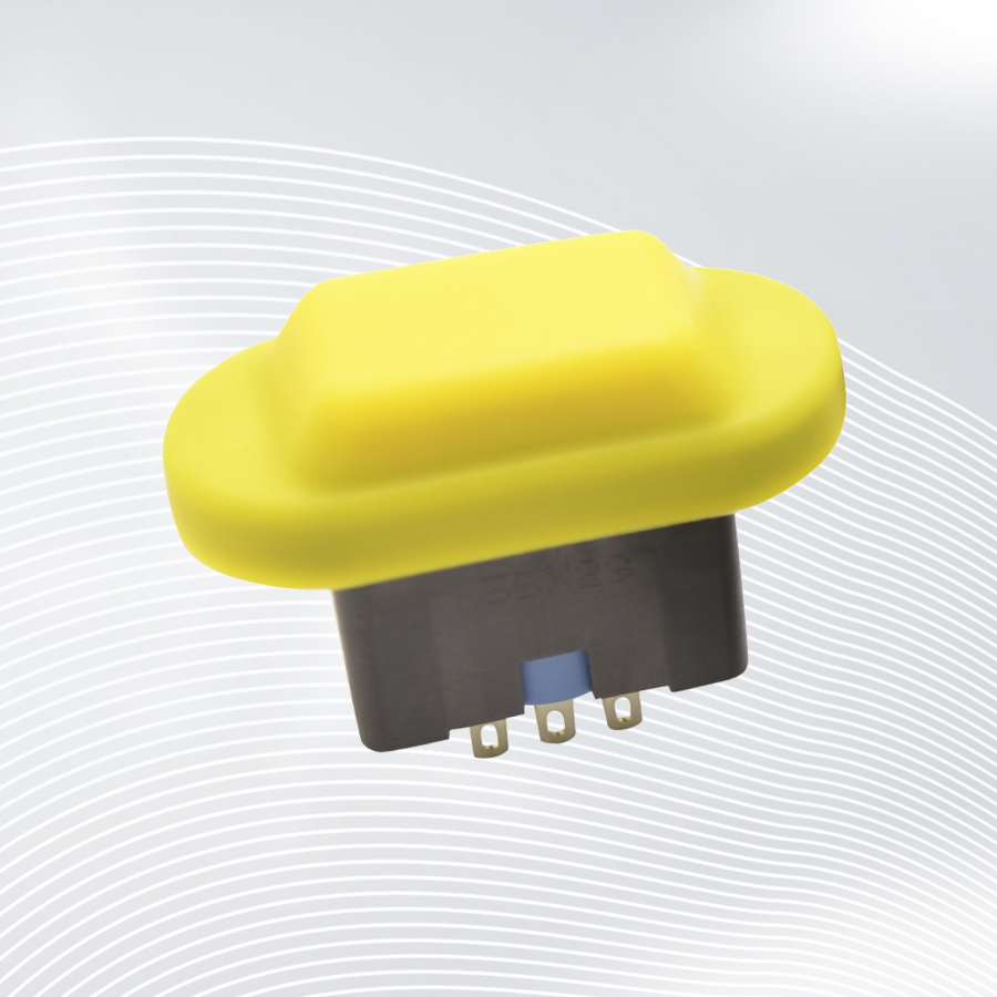
enabling switch ZA1

- 3 steps (OFF – ON – OFF)
- Ideal as enabling button on input devices
- 1 working contact (normally open contact)
- small size
- forced opening (stage 2 – stage 3)
- Contacts do not close during reset (Level 3 – Level 1)
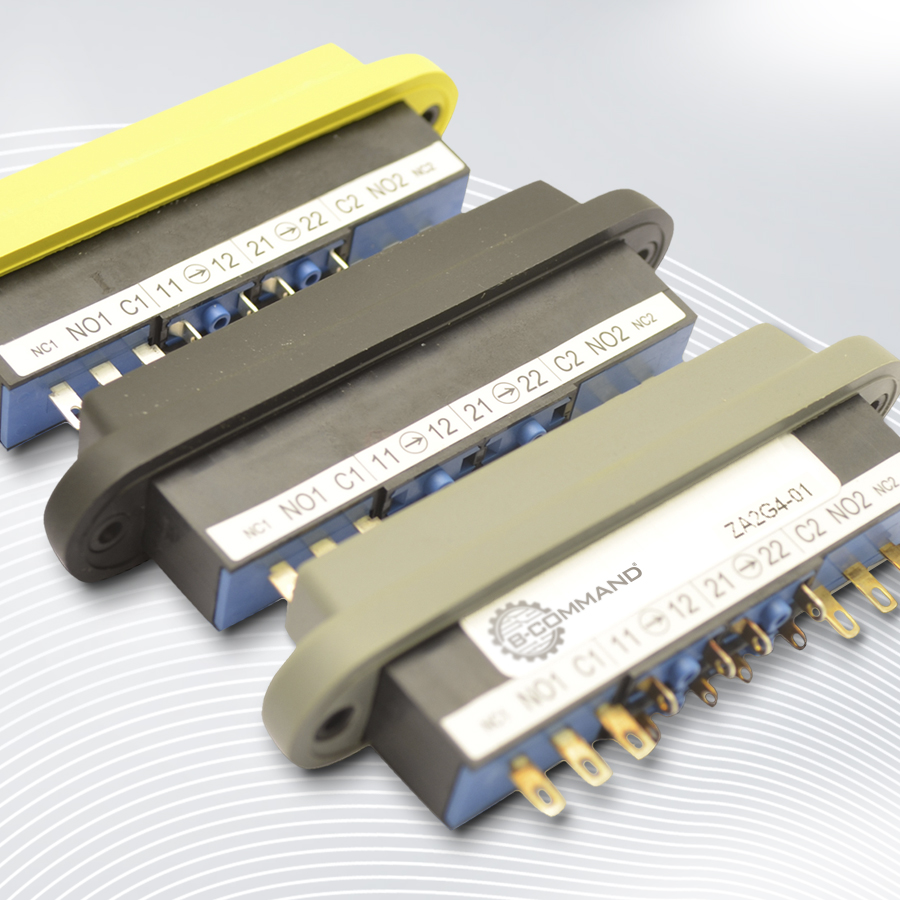
enabling switch ZA2

- 3 steps (OFF – ON – OFF)
- Ideal as enabling button on input devices
- 2 working contacts (changeover contact)
- forced opening of the auxiliary contacts (stage 2 – stage 3)
- Contacts do not close during reset (Level 3 – Level 1)
- Redundant contact configuration meets safety category 4
- Auxiliary contacts for monitor functions
- With rubber cap IP65 >/li>
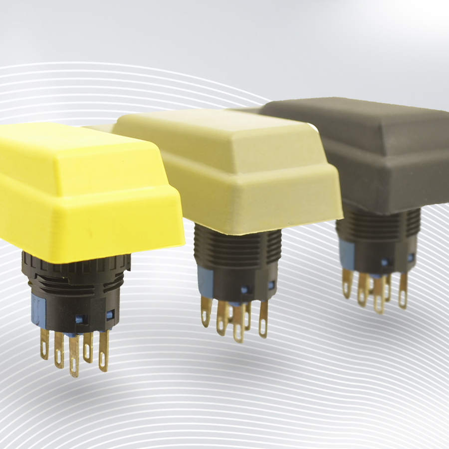
enabling switch ZA3 / ZA5

- installation dimension Ø 16 mm
- 3 steps (OFF – ON – OFF)
- Ideal as enabling button on input devices
- 2 working contacts (changeover contact)
- Contacts do not close during reset (Level 3 – Level 1)
- Redundant contact configuration meets safety category 4
- With rubber cap IP65
enabling switch ZA6

- 3 steps (OFF – ON – OFF)
- ergonomic design
- 2 working contacts
- Contacts do not close during reset (level 3 to level 1)
- Redundant contact configuration meets safety category 4
- protection class IP65
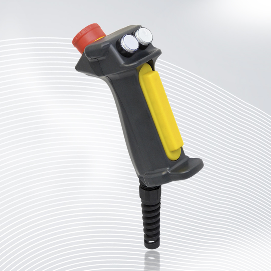
enabling switch ZB2

- 3 steps (OFF – ON – OFF)
- ergonomic design
- 2 working contacts –
- Contacts do not close during reset (Level 3 – Level 1)
- redundant contact configuration meets safety category 4
- Protection class up to IP67
- Optional signal lamp >/li>
- Optional buttons or key switches
- Optional emergency stop mushroom button
- solder connections
You have questions?
SEND US A MESSAGE
CONTACT INFORMATIONS
Follow us on our social media channels and get informed about new products.