


Rotary Limit Switches for Wind Turbines, Cranes and Winches
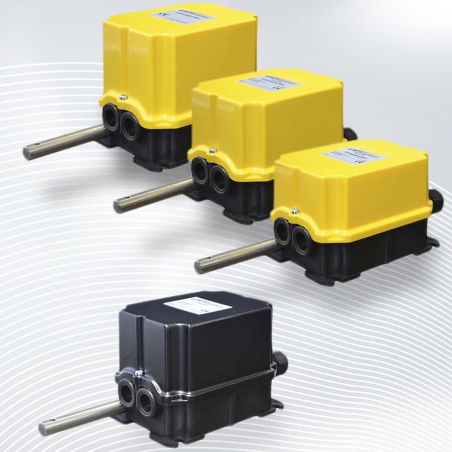

Geared limit switches for wind turbines, cranes and winches
Originally developed for limiting the end positions of overhead cranes or winches of crane hoists, gear limit switches have also been reprocessed and further developed for wind power applications. At B-COMMAND we offer both classic rotary limit switches for the end position limitation of crane hoists, as well as the next generation of gear limit switches, specially developed, tested and certified for use in wind energy.
Function of rotary limit switches
Geared limit switches control and measure the movement of industrial machines such as wind turbines, crane hoists and winches. The revolutions of the shaft are transmitted to a cam switch mechanism, through which mechanical switching contacts are actuated. This is why they are also called cam limit switches or rotary cam switches. All variants of the switching contacts are designed as auxiliary contacts. Turning the camshaft opens or closes the corresponding contacts. Our gear limit switches can be equipped with up to 12 switching contacts. The switching contacts are always of positive opening design in order to comply with the applicable standards in terms of machine safety. In addition, contact elements are available as normally open contacts (1NO), normally closed contacts (1NC) or also potential-free normally open + normally closed (1NO+1NC) contacts. Furthermore, the interior has been optimized for easy and quick wiring. With our optimized gear limit switches, it is therefore possible to realize unprecedented monitoring, control and switching functions.
Geared limit switches are mainly used where the rotary motion of industrial machines is to be monitored or limited. This includes the rotations of a shaft (e.g. winch, drive shaft, etc.) or the rotational movement of a complete machine (boom of a construction crane, rotating platform, nacelle of a wind turbine, etc.). For flexibility and quality in movement measurement and control, it is crucial that the cams can be individually and very finely adjusted to desired positions in order to flexibly define end positions and reference points. Furthermore, abrasion and rusting should be avoided, which is why the transmission and guide shafts of our switches are made of stainless steel.
All materials in direct contact with the environment are resistant to gases, oils and extreme temperature changes. The all-round rubber seal provides optimum protection against dust and water, so that protection class IP 66 and IP 65 can be achieved without any problems.
Geared limit switches for crane hoists
The end positions of a crane hoist are defined by the corresponding angle of rotation of the drive shaft. These revolutions can be translated into the angle of rotation of a cam limit switch. If, for example, the defined angle of rotation for the lower operating position of a crane is now reached, a signal can be transmitted to the cabin so that the lowering of the crane can be interrupted. If the crane operator reacts too late, a predefined angle of a so-called emergency end position is reached, whereby the drive is automatically stopped and the downward travel is interrupted. The rotation of the winch shaft is transmitted to the shaft of the gear limit switch, thus actuating the corresponding switch contacts at the previously set position.
In addition to the gear limit switch for limiting the lifting heights, cross lever limit switches can also be used. These are used to limit the movement of the trolley and/or the crane. In addition to the basic stop function of the cross travel for each direction via 2 contacts, we are also able to implement a slow down and stop function via 4 contacts. Furthermore, special switching configurations allow the exclusion of defined areas outside the travel range of the crane.
On installations with jibs, the jib must be mechanically limited. Here, geared limit switches can provide safe pre- and limit switching of a respective jib stage. Especially our FCN gear limit switches are used in crane construction.
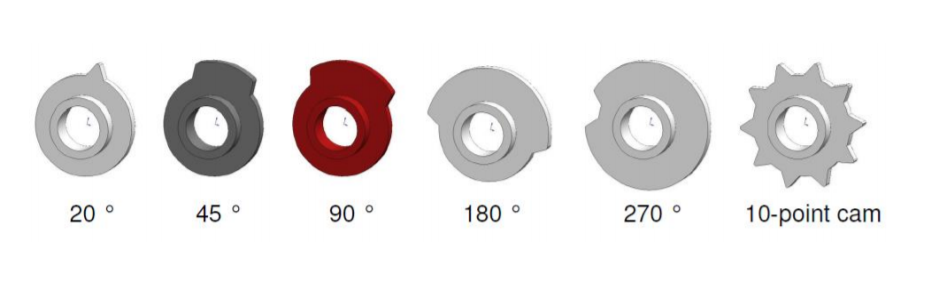
Each cam is equipped with its own adjusting screw (planetary gear). The individual screws operate only the cam connected to the screw without affecting the position of the other cams. The adjustment is made by simply turning the screw with a normal screwdriver. In this way, all cams can be adjusted safely and precisely to the desired position. As an additional service, we also offer pre-adjustment of all cams for our customers. Here, after the cams have been set, the shaft is fixed and only released again after installation at a predefined position in the system. This saves time and avoids errors during commissioning.
A completely new system of connecting the individual cams in the cam switch unit minimizes friction and at the same time increases the switching accuracy and reliability of the cams. The gear limit switches of the FCN series can be equipped with a maximum of 5 contacts. More than 15 different actuating cams are now available for actuating each contact. The following is an excerpt of our most frequently used cam types:
Geared limit switches for wind energy - yaw control (YAW) & more
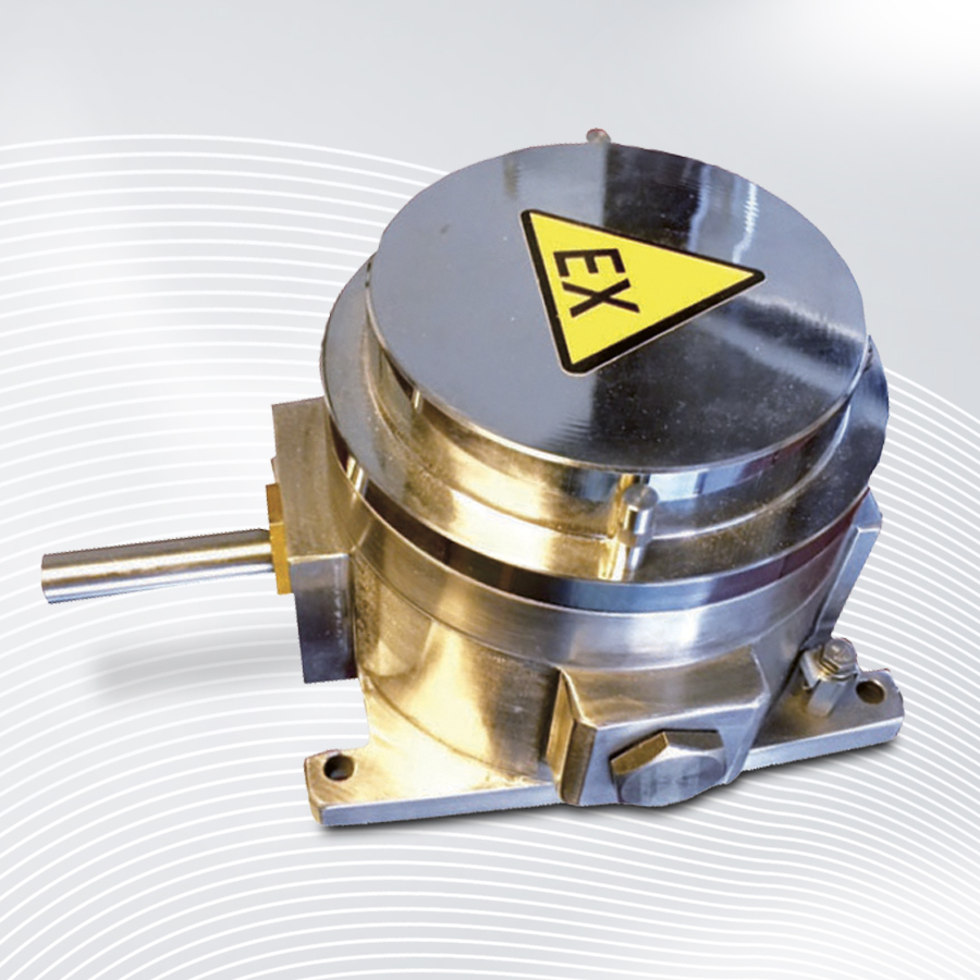
The FRM gear limit switches in particular have been specifically designed, tested and certified for wind energy applications. During the FRM design process, we were able to bring together a team with over 80 years of mechanical experience and 15 years of wind energy experience. The result is a new technology that uses only high quality components to meet the durability requirements of wind turbines.
All materials used are built for cold climates and are certified for -40°C operating temperature. The gearboxes of all gear limit switch series offer maximum accuracy with a minimum of hysteresis. New contact elements and special encoder solutions allow integration into modern industrial networks.
The geared limit switches are suitable for installation in all common interfaces such as PROFIBUS, PROFINET, IO-Link, CANopen and SSI. High-resolution encoder solutions enable a positioning accuracy of 0.001°.
The high quality of the products has been proven under all climatic conditions in all parts of the world – onshore and offshore.
Yaw-Control limit switch
To achieve maximum efficiency from wind turbines, it is necessary to keep the position of the rotor perpendicular to the wind. Yawing (controlling the yaw axis / yaw) of the turbine against the wind reduces the fatigue load and ensures longer durability of all components.
They are usually connected via a measuring pinion either directly to the yaw sprocket or connected to the drive pinion of a yaw motor. Gear limit switches fulfil two safety-relevant functions here:
The switch provides two general functions for yaw axis control:
Cable twist sensor (cable twist switch):
The cables connecting the nacelle to the ground components must be secured against twisting. If the turbine is turned in the same direction for a long time, the risk of twisting of the cables increases. The switch measures the twists and limits the end positions for each direction. This prevents twisting and tearing.
Yaw position control / wind tracking
Incremental or absolute encoders and potentiometers can be integrated to detect and continuously monitor the exact nacelle position, with an accuracy of up to 0.001°. The nacelle position signal generated by the limit switch, compared with the wind direction signal from the anemometer, enables the most efficient positioning for the most effective efficiency, i.e. high power output from the wind turbine.
Pitch-Control Limit Switch
The pitch control system is used to vary the angle of the rotor blades into or out of the wind. By changing the pitch of the blades, the speed of rotation and the power generated can be adjusted. When the power output reaches a critical value, the blade angle mechanism turns the rotor blades slightly out of the wind. As soon as the wind drops again, the blades are turned back again. The setting of the blade pitch has a great influence on the efficiency of the wind turbine.
The rotary limit switches are used to limit the end positions of the blade pitch, set pre-warning points and give precise position signals. These real-time position signals of the blade pitch enable the entire system to optimize the power output.
High-resolution encoders mounted directly in the switch are used for this purpose. Depending on the specification, different BUS systems can be covered.
The gear limit switch thus enables the combination of various safety-relevant tasks in just one application. This is also associated with savings in terms of costs and space requirements.
By using only one B-COMMAND rotary limit switch per leaf, all devices previously used for position monitoring can be saved (e.g. proximity switches and all mechanical devices required for this, i.e. limit switches and encoders on the motors).
By changing the blade angle of the wind turbine, the rotation speed and thus the generated power can be significantly influenced.
The main purpose of the gear limit switches is to generate an exact position signal of the blade position. The basis for an exact adjustment of the blade angle is the possibility to determine the instantaneous position with high precision.
Combination with sensors
The FRM gear limit switch has been developed to provide a high-precision platform for a wide range of sensors. By using the different gear designs together with the multifunctional mounting option for sensors, the FRM can be seen as an open base for all desired solutions. This was the main goal in the research and development for the FRM.
Encoders can be used to output signals such as SSI, CANopen, Profibus, Profinet etc. within the gear limit switches, which sends the specific signals to the appropriate controller. This makes it possible to output the current position of the system with very high precision in addition to the mechanical switching contacts that control the limitation of movement. By combining switching contacts and encoders, we can thus take care of movement limitation and position measurement in one device. A wide range of solutions are available for this, from simple potentiometers to SIL3 multiturn encoders with 35-bit resolution.

Measuring pinions and gear limit switches
Our measuring pinions are specially manufactured for use with encoders and gear limit switches. They are sold in conjunction with our FRS, FCN, FRM and FRX series of gear limit switches, but can also be adapted to any shaft size of absolute or incremental encoders.
The largest field of application for these products is wind power, where especially the blade or nacelle rotation is monitored with the help of these gears together with gear limit switches.
Rotary limit switches at a glance
FRS Rotary limit switch

- 4 switching contacts
- IP 65
- Disproportion from 1:10 to 1:175
- Operating temperature -20°C…+60°C
- 3 million switching cycles (service life)
- EN60947-5-1, IMQ CA02.03310
- Snap action contacts (1NO/1NC changeover)
FCN Rotary limit switch

- Ideal for crane construction
- 5 switching contacts
- IP 65
- Depreciation from 1:7.5 to 1:550
- Operating temperature -20°C…+60°C
- 2 million switching cycles (service life)
- EN60947-5-1
- Jump and creep contacts of different types
FRM Rotary limit switch

- Optimised for pitch and yaw control
- 12 switching contacts
- IP 66
- Disproportion from 1:14 to 1:900
- Operating temperature -40°C…+80°C
- 3 million switching cycles (service life)
- EN60947-5-1, IMQ CA02.03310
- Jump and creeping contacts of different types
You have questions?
SEND US A MESSAGE
CONTACT INFORMATIONS
Follow us on our social media channels and get informed about new products.