


Main switch for machine control - Load break switch with emergency stop function
Main switch for safe machine control & protection of personnel
Main switches are elementary switching and protective devices for safe machine control. They can be used, for example, as repair switches to quickly switch off large machines and systems so that maintenance work can be carried out safely. Or the emergency stop function can be used to protect equipment and operating personnel in hazardous situations and against overcurrent, faulty switching and electric shocks. At the same time, they are also used for autonomous, safe and gentle control of machines, or for simple manual switching on and off. By the way, all of us use load-break switches every day, namely the light switch. Strictly speaking, however, this is usually a pure load-break switch.
There are various types of main switches, namely load-break switches, circuit breakers, load switches, disconnectors and pure emergency stop switches. Load-break switches, also called repair switches or emergency stop switches, combine several of these functions. They are at once a load switch and a disconnector.
While load switches describe all those main switches that are used for the simple and above all manual opening and closing of circuits by hand (e.g. light switches), disconnectors (short: isolators) function, among other things, as protection against unintentional opening and closing under high load. They are also called high-voltage switches and have a very small switching capacity, while the switch position is always clearly visible. They also have the already mentioned switching fault protection in case of overcurrent. Unlike load switches, disconnectors can be used for switching and controlling motors, i.e. machine control.
Load-break switches now combine – as the name suggests – these both switch types and fulfil both the requirements for autonomous machine control (e.g. as protection against short circuit and voltage flashover)and the requirements for manual operation or opening and closing circuits by hand(i.e. closing and opening circuits by hand). as protection against short circuit and voltage flashover), as well as the requirements for manual operation or the opening and closing of circuits by hand(i.e. for switching machines or motors on and off). In this way, they protect machines from overcurrent and can simultaneously be used as emergency stop switches or repair switches to quickly and reliably switch off industrial plants. For example, in the event of pending repair work, or to protect employees from electric shock or an accident. In other words, they serve to switch and protect equipment and operating personnel in equal measure. For this purpose, they function within the scope of disconnection, switching of short-circuit currents (protection against overcurrent and electric shock) and as load switches for motors (on and off switches).
Another type of main switch is the so-called circuit breaker. Unlike all other main switches, these are also suitable for high currents and can hold these short-circuit or overload currents for the specified period of time in order to then safely switch off the machine without harming the motor or personnel. There are two types of circuit breakers, namely ACBs(Air Circuit Breaker) and MCCBs (Moulded Case Circuit Breaker). In German, they are also called open circuit breakers or compact circuit breakers. The main difference here is the enclosure. MCCBs have a housing made of insulating material, which encloses all components of the main switch, while ACBs are designed to be able to keep the main contacts closed for as long as possible. They are therefore air-insulated and available for fixed installation or as switches with chassis (withdrawable technology).
Tasks of load break switches in the machine control
In the machine control of motors, so-called voltage flashovers can quickly occur. These manifest themselves in so-called switching arcs. These always occur when two current-carrying parts are not sufficiently far apart or have not been sufficiently insulated. By the way, this does not necessarily have to be two components. The characteristic arcs are known, for example, from the overhead lines of railway systems. If a person steps too close to these high-voltage lines, the arcing also occurs. On the one hand, this can belife-threatening for people, but it also shortens the life of the machine components affected by unwanted voltage arcs, if it does not even directly destroy them.
If you now interrupt a current flow with a main switch, a voltage flashover can also occur here, namely between the contacts. During disconnection, the distance between them is not sufficient for effective insulation. An arc occurs when there is gas between the two contacts, as this is ionised to a high voltage difference and the gas discharge takes place as an arc. And this is exactly the danger for operators and machines, which load break switches prevent. The arc created by the interruption of the current flow continues to conduct current between the components despite the disconnection, so much so that they are completely destroyed or at least damaged.
This is precisely where circuit breakers and switch-disconnectors come in. They are equipped both with corresponding protective mechanisms that prevent voltage flashover and with components that enable the switching of the machine control. They can therefore simultaneously protect components and persons and control the switching of the equipment.
Load-break switches are efficient and multifunctional.
Main switches are used as switch-disconnectors especially in low-voltage distribution systems. Here, the installation of a switch-disconnector makes it possible to dispense with normal disconnectors in the machine control of your equipment. Load-break switches are therefore not only safe and effective, but also economical and efficient, especially in small switchgear.
They increase safety compared to disconnectors, can be used in combination with attached high-power fuses, i.e. the circuit breakers, can also be used in networks with higher short-circuit powers and enable in the medium-voltage range the switching of unloaded and loaded transformers, cables and overhead lines, as well as of reactive current compensation capacitors. In addition, they can also be used for coupling busbars. In the low-voltage range, they are additionally ideal for interrupting main circuits of the main distribution, i.e. also as emergency stop switches.
They are also known as repair switches because they make it possible to take equipment off the mains independently of the circuit breaker, which saves an enormous amount of time. This function also enables main switches to be used as emergency stop switches, although they have to fulfil some special requirements.
Which regulations govern the requirements for main switches?
Since a main switch used as a switch-disconnector combines several functions, various regulations and standards apply here. The harmonized IEC/EN 60204-1, VDE 0113 Part 1 describes the general standards for the entire electrical equipment of machines and serves above all to comply with the safety objectives of the EEG Machinery Directives. Part of these directives are also the standards and regulations for main switches and switch disconnectors. The common CE marking indicate whether systems and machines, as well as other equipment and electrical components, comply with these directives. The definition of the term “machine” is also regulated here. According to Annex A of IEC/EN 60204-1, which contains a list of typical examples of machines, a machine is the entirety of connected parts and devices, of which at least one component is movable. However, the line between machine and equipment is often very narrow. It is important to differentiate between these two types of systems, since strong systems must be equipped and secured in accordance with the DIN VDE 0100 standard.
In order to avoid this sometimes difficult distinction, IEC/EN 60204-1, which covers all requirements at the same time, is often applied in case of doubt.
Additional expenditure of IEC/EN 60204-1 compared to DIN VDE 0100:.
- Main switch (mains disconnection devices)
- Control transformers
- Risk assessment
- Prescribed conductor colors
- Protection against automatic restart
- Increased requirements for emergency stop switches
When choosing the ideal switch-disconnector it is therefore important that it ideally meets all the relevant requirements of IEC/EN 60204-1, i.e. above all it combines the function of main switch, protection against automatic restart and the emergency stop circuit.
Every disconnection of electrical equipment such as systems and machines must be effected by a main switch. It is therefore mandatory. Circuit breakers and switch disconnectors are most often used as main switches, as they combine several functions. Therefore, the standards are also regulated in various IEC/EN regulations. They divide themselves into isolator characteristics (device standard IEC/EN 60947-3) and main switch characteristics (device standard IEC/EN 60204-1). A main switch is not required for machines with a maximum capacity of 16A. Its function in this power and voltage range can be fulfilled by a simple “plug and socket” device
The most important regulations for main switches at a glance:
- It may only have the switch positions ON and OFF.
- If the main switch is in the OFF position, it must also be lockable
- The TRIGGER position is not considered an additional switch position and is permissible
- For this, the isolator properties must already be ensured with the main contacts open in the TRIGGER position
- Main switches must not be lockable in the TRIPPED position
Our main switches work with rated currents according to AC-21A. They can be used in industry, trade and building services engineering. You can also obtain variants from 16A to 250A.
Especially the lockability of the main switch in the OFF position is elementary, among other things to prevent accidental switch-on by the operating personnel, e.g. when maintenance work is being carried out on the machine. The TRIGGED position is optional, but has the great advantage that it is possible to identify from a distance whether the switch has been triggered, e.g. by a short circuit.
Since machine control systems are designed very individually, the main requirements are the optimal use of the mounting surface and the optimal routing of the main power connection . There are also recommended installation heights especially for machine controls. The colors of the handles and the switch are also prescribed. They may and must be kept only in red and yellow if it is a main switch that can also be used as an emergency stop switch.
Using switch-disconnectors as main and emergency stop switches - which requirements apply?
If the switch-disconnector is used as the main switch for the emergency stop or emergency stop function, i.e. as a panic switch / emergency stop switch, there are some technical and external regulations which it must meet compared to control circuits and the function as a disconnecting or load switch. For example, the operating elements must be kept in red and yellow. On the other hand, if it is not an emergency stop switch, the actuators can also be black or gray.
Requirements for main switches:
-
- a manually operated main switch must be provided for each feed
- with two or more main switches, protective interlocks must be used
- as main switch are permitted:
- Switch-disconnectors with isolating characteristics according to IEC/EN 60947-3
- Switch disconnector with auxiliary contact
- Circuit-breakers according to IEC/EN 60947-2, suitable for disconnection according to IEC/EN 60947-3
- may have only one ON and only one OFF position, which in turn must be clearly marked with 0 and I
- In addition, a triggering position is permissible but not mandatory
- visible isolating distance or position indicator, which cannot remain in the OFF position and can be locked as long as not all contacts are actually safely open
- If the main switch used is not a combined emergency stop switch, the outer handle must not be red (black or grey recommended)
- must be lockable in the off position
- all active conductors must be disconnected from their mains connection. Only in the case of TN systems can the neutral conductor be disconnected or not disconnected from the grid connection
.
- the breaking capacity must be sufficient to disconnect the current of the largest motor in blocked state together with the sum of the operating currents of all other motors and/or loads
- power operated circuit breakers may be used as main switches. In this case, they must have a device for manual operation. Manual manual and remote closing must not be possible in the OFF position
requirements for main switches, which are also used as emergency stop switches:
-
- On certain machines, the main switch may be used as an emergency stop switch
- all operating elements for switch disconnectors used as emergency stop switches must be red
- If there is a background behind the control unit, i.e. a housing, this must be yellow in those places where the mains disconnection device can be directly operated to switch off in an emergency. It must also be easily accessible
.
Many switch-disconnectors have additional components which enable e.g. a manual or also autonomous and event-controlled remote tripping in case of overcurrents or voltage flashovers. Such an additional component also includes, for example, the undervoltage release.
Advantages of main switches with undervoltage release
Undervoltage releases are a great advantage, especially when remote releases are required to improve safety in the control of machines and systems, as well as occupational safety. While many switch-disconnectors work with shunt releases, which are only monitored for their functionality when normal operation is running, the undervoltage release works according to the quiescent current principle. This means that it is always under voltage (and with it the entire release circuit) and not only when the operating current flows. As soon as the voltage fails or e.g. a conductor breakage occurs, the main switch with undervoltage release switches off, i.e. interrupts the electric circuit. This high safety, due to the increased sensitivity, is also called “fail safe”. This protects also before the automatic restart after a power failure and the voltage recovery, as prescribed by IEC/EN 60204-1.
However, there is also an important disadvantage or sensitive point in the case of main switches with undervoltage release, which can, however, be compensated for with the aid of tools. If it is used as a main switch, it normally taps the required voltage from the supply network on the supply side of the switch. As a result, even when the main switch is turned off, the trigger circuit is connected to a voltage that is dangerous to touch as mains voltage. The danger of a current shock exists. However, this can be prevented by equipping the main switch with a additional 2-pole leading auxiliary switch. After the main switch has been switched off, the majority of the trip circuit for the undervoltage release will also be de-energized.
A main switch with undervoltage release is also advantageous for protection against short circuits. It must be planned how a trip circuit is to be protected against short circuits. This is where the emergency stop function with its corresponding release circuits comes into play. Especially when a so-called emergency stop circuit is sent across the switchgear and outside the switchgear cabinet, it must be protected against short circuits. In this case, a protective device must lead to safe failure – i.e. to disconnection. While a shunt opening release becomes ineffective when overcurrent protection is activated, an undervoltage release continues to function. However, this is only decisive if the emergency stop circuit operates far outside the control cabinet. If, on the other hand, the release circuit remains limited to the narrow surroundings of the main switch, then short-circuit-proof and safe wiring may be sufficient.
Main switch as short circuit and overload protection
The term overcurrent protection summarizes the terms short circuit and overload protection. Overcurrent protection devices are required for this purpose, e.g. automatic circuit breakers, motor protection switches or even circuit breakers or switch disconnectors with a corresponding function. Main switches have decisive advantages over fuses. Fuses must be procured in the respective country of use. This is not always easy, especially with internationally operating companies or cooperations, which is why fuseless circuits are preferred. They are also recommended in the corresponding guidelines. Depending on the voltage, however, in some cases higher quality circuit breakers must be used instead of the equally adequate load-break switches.
Which types of switch disconnectors does B-COMMAND offer?
The individual series of switch-disconnectors differ mainly in the type of installation or mounting and the color scheme, because emergency stop switches must be kept in yellow and red, while switch-disconnectors without emergency stop function are recommended in black and gray.
The customer can choose between 3-pole and 8-pole versions. Current ratings from 10A to 320A are available.
The Team of B-COMMAND GmbH has a long history in the field of control and safety technology, especially in crane and lifting technology and wind energy. The production and sales focus is on electrical engineering products for a wide range of applications. Especially switch disconnectors and cam switches play a major role in electrical engineering. Since 2007, we have been offering a selection of main switches with the Eco-Line program for some application areas. With the new program we are able to cover all applications and also all required approvals. Made in Germany – our commitment. All premium switch-disconnectors of the program presented below are designed and produced in Germany. We thus ensure the high quality and short delivery times for our customers.
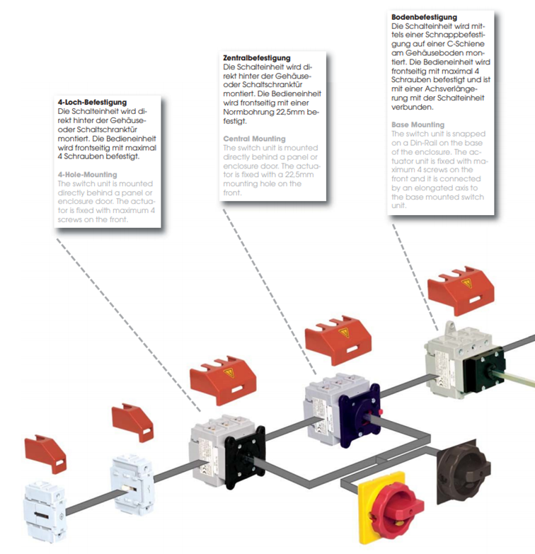
- 4-hole mounting: The switching unit is mounted directly behind the housing or control cabinet door. The operating unit is fastened at the front with maximum 4 screws
- central mounting: The switching unit is mounted directly behind the housing or control cabinet door. The operating unit is fastened at the front with a standard 22.5mm drill hole
- The switching unit is attached to the bottom of the housing by means of a snap-on mounting on a C-rail on the bottom of the housing. The operating unit is fastened at the front with a maximum of 4 screws and is connected to the switching unit with an axial extension.
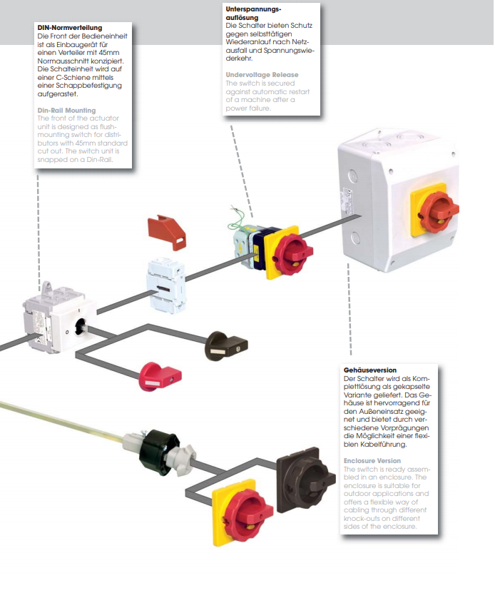
- DIN standard distributor: The front of the control unit is designed as a built-in unit for a distributor with a 45mm standard cut-out. The switching unit is snapped onto a C-rail by means of a snap-on mounting
- The switches offer protection against automatic restart after power failure and voltage recovery.
- The switch-disconnector is available as a complete solution as an encapsulated version. The housing is excellently suited for outdoor use and offers the possibility of flexible cable routing through various pre-stamping options.
Our main switches / emergency stop switches meet both the requirements for the mains disconnection device according to point 5.3, as well as the regulations for load disconnection switches according to AC 23 B. Furthermore, the requirements for devices for Emergency Stop according to point 10.7 and devices for Emergency Stop according to point 10.8 are also fulfilled. The requirements for emergency stop and emergency stop include, for example, the fact that the corresponding switch-disconnectors must be positively opening (IEC 60947-5-1). For switchgear with undervoltage release, the response limits of the undervoltage release are specified in EN 60947-1 section 7.2.1.3, which our main switches also comply with.
undervoltage releases, which are assigned to a switchgear device, must cause the opening of the device at a value between 70% and 35% of their rated voltage. And this is also the case when the voltage drops slowly. It must be possible to close the device when the supply voltage is equal to or higher than 85% of the rated voltage.
Applications of switch disconnectors
Primarily switch-disconnectors serve as main switches for switching and protecting equipment and persons, both in private and industrial applications. They primarily perform the task of disconnecting, switching short-circuit currents, load switching and protecting electrical equipment against overcurrent and persons as protection against electric shocks. A switch-disconnector must at least comply with the utilization category AC-23B.
Switch disconnectors can also be used as emergency stop switches in private homes, or for example in the workshop or the hobby musician’s room to switch all sockets on and off simultaneously. Or to switch on a compressor in the garage or workshop. There are countless other examples of both professional and simple systems for a hobby electrician.
Switch disconnector 3-pole or 4-pole?
Our switch-disconnectors are available in 3-, 4-, 6-, or 8-pole versions. Which version you need depends of course on the requirements on the switchgear, i.e. whether all outer conductors or also the neutral conductors are to be monitored and switched. The number of conductors also has a corresponding influence on the question of which version of the switch-disconnector you must use.
versions are 3-pole and 4-pole load-break switches. The aim of a three-phase alternating current network is to avoid harmonics. If all currents of the outer conductors have the same current intensity, they cancel each other out due to the phase shift in the neutral conductor. If, however, these phase shifts occur between the currents of the outer conductors, harmonics are generated, which leads to superimpositions in the neutral conductor that produce a current intensity that is higher than the highest value of the outer conductor. A conductor fire can be the result.
In practice, it often happens that the currents in the outer conductors do not all have the same strength and load the outer conductor asymmetrically. This results in a strong compensating current on the neutral conductor. This current strength of the compensating current may correspond maximum to the highest current strength of an outer conductor .
3-pole load break switches are used when the neutral conductor does not need to be monitored. This is the case when a symmetrically designed system has to be protected.
If, in addition to the external conductors, the neutral conductor must also be monitored, at least one 4-pole load disconnecting switch is used. This is the case if there is an unbalanced load on the outer conductors or if there is a risk of harmonics from the neutral conductor.
In addition, there are also 3-pole switch-disconnectors, which only monitor the three outer conductors, but additionally disconnect the neutral conductor when tripped in case of a shear load. These main switches are marked 3P+N.
What you should consider when buying a main switch
- What should the switch be used for? Only for manual switching, e.g. as a maintenance or repair switch, or should it also take over an autonomous protective function in the machine control system ?
- How high are the voltages to which the main switch is subjected? For high voltages down to 250A, it is advisable to use a circuit breaker instead of a switch-disconnector.
- Before buying, develop a circuit concept, e.g. to plan the protection against short circuits of a possible emergency stop circuit. This protection depends on where the trip circuit is located – in the close vicinity of the switch cabinet or far outside. The question of whether the outer conductors are symmetrical or asymmetrical must also be clarified. This is the only way to select the switch-disconnector according to whether only the outer conductors or also the neutral conductor must be monitored
- .
- The working environment and pressure or temperature conditions must also be taken into account! All our main switches work at an operating temperature between -20°C and +50°C.
- If the Strong switch-disconnector is also to function as an emergency stop switch, the Strong actuator must be red and the background Strong yellow.
- approvals of our switch disconnectors: CE, UL, CSA, VDE, GL, DNV, LLoyd
A wide range of different types for all applications are available from stock in Hamburg at any time. Further information and product examples can be found in our catalogue.
Our main switches at a glance
4-hole mounting

- 3-, 4-, 6-, or 8-pole version
- 16A to 250A
- red or black actuator >/li>
- protection class IP65 (front side)
- operating temperature -20°C…+50°C
- Approvals: CE, UL, CSA, VDE, GL, DNV, LLoyd
Central Fastening

- 3-, 4-, 6-, or 8-pole version
- 16A to 250A
- red or black actuator >/li>
- protection class IP65 (front side)
- operating temperature -20°C…+50°C
- Approvals: CE, UL, CSA, VDE, GL, DNV, LLoyd
Floor Mounting

- 3-, 4-, 6-, or 8-pole version
- 16A to 250A
- red or black actuator >/li>
- protection class IP65 (front side)
- operating temperature -20°C…+50°C
- Approvals: CE, UL, CSA, VDE, GL, DNV, LLoyd
DIN standard distribution

- 3-, 4-, 6-, or 8-pole version
- 16A to 250A
- red or black actuator >/li>
- protection class IP65 (front side)
- operating temperature -20°C…+50°C
- Approvals: CE, UL, CSA, VDE, GL, DNV, LLoyd
Housing version

- 3-, 4-, 6-, or 8-pole version
- 16A to 250A
- red or black actuator >/li>
- protection class IP65 (front side)
- operating temperature -20°C…+50°C
- Approvals: CE, UL, CSA, VDE, GL, DNV, LLoyd
ECO-Line

- 3- or 4-pole version
- in housing or for installation
- CE approval
- protection class IP65 (front side)
- operating temperature -25°C…+70°C
- 10A to 100A
You have questions?
SEND US A MESSAGE
CONTACT INFORMATIONS
Follow us on our social media channels and get informed about new products.